Solenoid Tester


{Copyright (C) 2007 Avanquest Software, Inc. All Rights Reserved}
GEI Systems, Inc
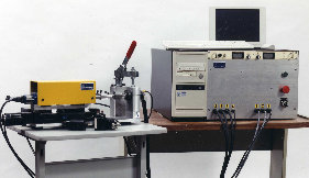
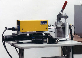
With the only one button to push, the unit will perform the following test phases:
- Phase #1: Computer energizes the solenoid's coils and measures the amount of the "total travel" plunger moves. It also measures the hold-in and pull-in coils resistance.
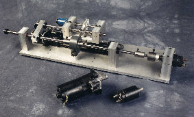
- Phase #2:. Power is removed from the ignition key terminal but a small amount of voltage is applied to the battery terminal. The linear actuator moves the plunger into the solenoid and measures the amount of load it requires to compress the spring by reading load cell to determine the spring rate and the over travel displacement.
- Phase #3: (main contact resistance). Power is applied to the ignition key terminal and a battery terminal. The solenoid will close the main contacts so the current will flow through the main contacts to the motor terminal. During this test the computer measures the voltage drop across the main contacts and amount of current going through them. Those two parameters define the main contact resistance and indicate the conditions of the surface at those contacts.
- Phase #4: (Low Voltage Test). Any external load is removed from the solenoid and the desired low voltage (5VDC) applied to the Ignition Switch terminal. Solenoid must completely engage under this condition to be accepted.
- Phase #5: (Load Test). If all above tests are within the spec, computer will engage the linear actuator to apply an initial the load (5 -6 lbs) to the solenoid plunger. Then the desired voltage (8 - 10VDC) applied to the Ignition Switch terminal. Solenoid must engage. During next few seconds, the computer ramps up the load until the desired level (20-30 lbs). During this phase, the solenoid must continue to be engaged and not exceed the max. amperage level.
Phone:(612) 922-7816
Fax: (612) 920-7955
E-mail: info@geisystem.com
Fax: (612) 920-7955
E-mail: info@geisystem.com