Testing Philosophy


{Copyright (C) 2007 Avanquest Software, Inc. All Rights Reserved}
GEI Systems, Inc
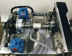
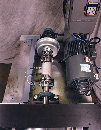
Every tester we have developed is based on the traditional configuration well known in testing industry as a dynamometer type test. This configuration requires two major computer controlled modules attached to the component to be tested which we refer here to in general term as the "specimen". One module is attached to the "input" of the specimen and the second one to the "output". In this configuration the tested component is placed between these two computer controlled elements which control the test's conditions. Sometimes, there are requirements for other active elements which can modify testing conditions or as we call them - environmental conditions.
ALTERNATORS:
input module- DC motor supplies RPM to the shaft
output module- Electronic load attached to the alternator output to simulate demand for amps
STARTER MOTORS:
Input model- Programmable power supply to simulate the battery
Output module- Load device at the output of the starter in the form of a DC motor, magnetic particle brake or mechanical brake
Here are examples of other choices for GEI Systems testers as the input and output modules, depending on the nature of the application:
ELECTRICAL FUEL PUMPS:
Input module-Programmable power supply
Output module-Flow control valve at the output port
POWER STEERING PUMPS:
Input module- DC motor at the input shaft to simulate the engine RPM
Output module-Flow control valve
Input module-Programmable power supply
Output module-Flow control valve at the output port
POWER STEERING PUMPS:
Input module- DC motor at the input shaft to simulate the engine RPM
Output module-Flow control valve
we have to attach a drive source to the input shaft of the transmission and an active load to the output shaft. The most common source for RPM in our testers is a variable electrical motor such as a vector drive which can be interfaced to and controlled by a computer. A hydraulic motor can be used for this purpose as well. The output module as a source of load (force or torque) can be implemented by a variety of components: DC drive, magnetic particle brake, hydraulic motor/pump, pneumatic/mechanical brake, eddy current brake or even water brake.
Regardless of the physical nature of these components, the main goal during this test is to provide a given RPM at the input shaft with a desired load applied to the output of the "gear box". A network of feedback sensors are attached to the powertrain being tested to monitor the test condition. This allows the system to store information for analysis in real time or off line, depending on requirements.
At the end of, or during the test this information is compared with a set of established parameters based on desired specifications and used for specimen acceptance, sometimes reduced to a Go/NoGo decision.
At the end of, or during the test this information is compared with a set of established parameters based on desired specifications and used for specimen acceptance, sometimes reduced to a Go/NoGo decision.
Phone:(612) 922-7816
Fax: (612) 920-7955
E-mail: info@geisystem.com
Fax: (612) 920-7955
E-mail: info@geisystem.com
Powertrain testing.
In the case of a transmission or any other type of gear box,